At Electron Energy Corporation (EEC), our engineering team works closely with customers to provide a virtual in-house magnet technology resource when it comes to prototype design and fabrication. We use 2D and 3D Finite Element Analysis (FEA) to solve the most demanding engineering problems. Also, our in-depth knowledge of magnetic materials and decades of practical magnet and magnet assembly experience enable us to provide innovative solutions for our customers and ensure that their precise magnetic requirements are met.
Why use FEA?
FEA offers many advantages over traditional trial-and-error prototyping, helping you bring your product to market faster:
- FEA is more cost effective than making prototypes.
- FEA can provide faster solutions than prototyping.
- Using FEA, the design can be optimized.
- More alternative designs can be examined to improve quality, increase product life, and customer satisfaction.
At EEC, we have applied our design expertise to electric motors, generators, magnetic bearings, magnetic couplers, magnetic seals, guidance systems, mixers, traveling wave tubes, and medical devices for private sector customers and government agencies. We strive to be a perfect extension of our customers’ engineering departments. Our strong engineering capabilities have made us the industry leader worldwide, and we are continually developing new products to meet changing customer needs.
Following are some examples of our magnetic designs:
Motors and Generators
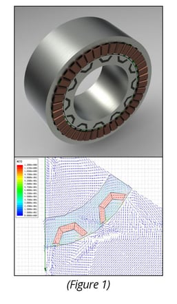
EEC conducted FEA for the design and performance prediction of various PM (permanent magnet) rotary machines (e.g. brushless DC/AC motors, brushed DC motors, interior PM motors, and synchronous motors). FEA enables us to evaluate new topologies to meet the desired power requirements, torque profile with low torque ripple, back EMF waveform, and other motor performance characteristics. Figure 1 shows an example of an IPM (Interior PM) motor using FEA for design and optimization considerations. EEC has designed a brushless IPM motor with high saliency ratio for a NASA SBIR Phase II program (grant # NNC06CA04C). A variety of generator designs also have been analyzed at EEC using 3D FEA, including axial and radial flux machines.
Magnetic Bearings
Magnetic bearings technology is considered to be an enabling technology for new advanced engine designs. It eliminates the need for lubrication and increases machine reliability. A magnetic bearing can be designed via iterative search employing 3D finite element based electromagnetic field simulations. FEA can provide the force-current relationships, maximum load capacity of the bearings, required saturation flux levels, losses, etc. Optimization of weight, performance and cost can be achieved by skillful numerical analysis. For example, an ultra-high temperature magnetic bearing was designed and built to produce 500 lbs of force at 538°C by EEC and Texas A&M University for a NASA SBIR Phase II program.
Magnetic Couplers
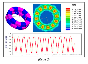
Rotary magnetic couplings are commonly designed in two configurations: co-axial and face-to-face. The torque characteristics of a magnetic coupler can be investigated and optimized by FEA using 3D electromagnetic field solver. The coupling torque is related to magnetic performance of PMs, number of poles, air gap, and the magnetic circuits. For fixed air gap magnetic coupler, FEA can help determine the best magnetic circuit design options. Figure 2 shows a conventional 12 pole face-to-face PM coupler model.
Traveling Wave Tubes
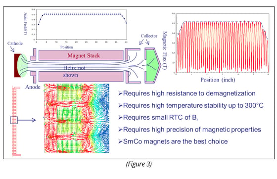
Traveling wave tubes (TWTs) amplify radio frequency waves by converting electron beam energy into microwave energy. We have used FEA to design the magnet stacks to achieve pre-determined axial field profiles. Figure 3 shows a typical axial field profile of the magnet stacks for TWT applications.